


Contact Us
Temperature Transmitters
Wire Harnesses
Temperature Sensors
Fiber Optic Sensor Systems (Partner Company)
Thermocouple/Extension Wire
Temperature and Process Controllers
Specialty Metals


Whitepapers / Selecting the Right Thermocouple
Used every day by most processors, thermocouples tend to be taken for granted. Many processors don't know the range of types available or how to make the optimum selection for the job. Here's one supplier's view of what to look for, both in conventional thermocouples and in newer designs that reportedly offer greater accuracy and can help save energy, boost output, and improve product quality.
In the majority of plastics processes, accurate control of temperature is fundamental to maintaining control of throughput rate and product quality. Because so much energy is consumed in generating and removing heat in many processes, good temperature control is also necessary to keep a grip on energy costs. Many problems in temperature control can be traced back to one of the most basic and universal tools of temperature control the thermocouple. All the sophisticated electronic hardware and software in the world won't achieve the goal if the temperature to be controlled is not sensed accurately in the first place. And to do that requires proper application of the right type of thermocouple for that particular sensing task.
The aim of this article is to update those who may be unfamiliar with today's wider range of thermocouple options, focusing on applications in injection molding, extrusion, and blow molding. It will describe the two main conventional types of thermocouples for these processes, and some newer versions that have become widely available only recently. Some of these new designs for the first time allow the temperature of the part itself to be measured in the mold.
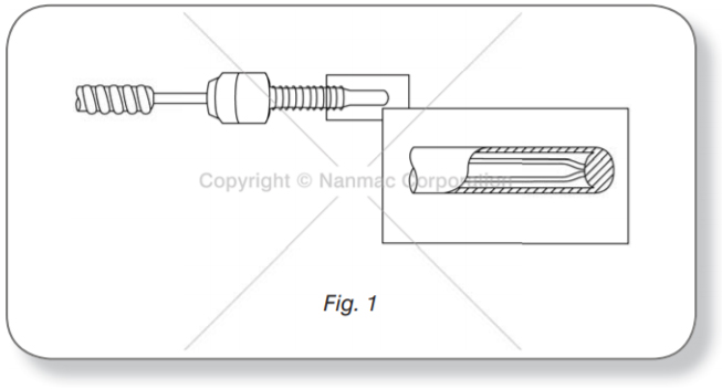
Figure 1 shows the bayonet-type thermocouple, which is commonly used to measure temperatures in the extruder barrel and molding machine nozzle. This usually is a 3/8 in. OD, stainless-steel, tubular thermocouple with an electrically grounded thermal junction. It is spring loaded to ensure good thermal contact with the bottom of a blind hole. Sometimes the tip is a silver alloy to improve contact and heat flow characteristics.
This type of thermocouple assembly in pocket depth installations up to P/a in. has inherent errors caused by the depth of the pocket, nipple cap, air currents in the vicinity of the heated cylinder, and the position of the thermocouple relative to the top, bottom or side of the heated cylinder. Controlled tests (Ref. 1) have shown the following errors with bayonet-type thermocouples:
- Air drafts caused by open doors and windows, air circulating around heated cylinders and cooling air caused errors of up to 90° F in thermocouples installed in pocket depths of Vz in. using conventional-style, twist-lock nipples.
- Errors from 7° to 36° F were observed simply by positioning the thermocouple in the top, bottom or side of a heated cylinder. An error in measurement was also noted with respect to the type of nipple used to install the thermocouple in the wall. All thermocouples in this test were also at pocket depths of V2 in.
- Errors of 18° F were measured in pocket depths of 1/2 in. In pocket depths of 1/2 in. the error was reduced to about 4° F.
The additive effects of these errors can easily create an overall error of 90° F or more in shallow depth applications of conventional bayonet-type thermocouples. Clearly, then, a more precise temperature sensor is needed, particularly in applications where the pocket depth is 1/2 in. or less.
One of the newer thermocouple designs, a “right-angle” ribbon type, was specifically developed to eliminate conduction errors caused by temperature gradients. This design is a thermally isolated or adiabatic probe that will measure the actual local temperature independent of conduction effects. Controlled gradient tests have shown no measurable errors in temperature. In addition, response times are a few milliseconds.
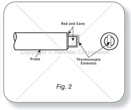
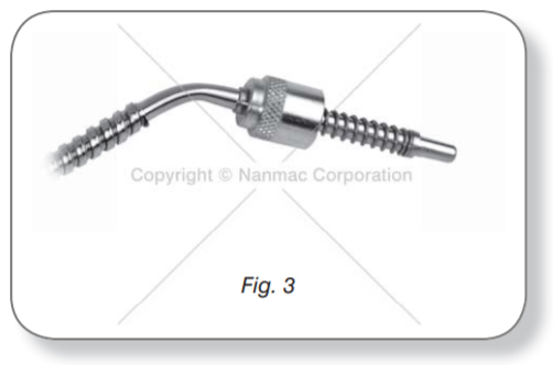
Figure 2 shows the essential features of a right-angle thermocouple. Note that the sensing element consists of exposed ribbon thermocouple elements and ceramic substrata. The ribbons in the vicinity of the thermal junction are parallel to the plane of the heat source; thus, both the thermal junction and the extension ribbon leads are heated simultaneously, eliminating conduction errors. Since the ribbon design offers the maximum surface contact area to the bottom of the heated blind hole, it also exhibits fast response times. Figure 3 shows a typical bayonet-type thermocouple which has been modified with ribbon sensing elements. It is designed to replace conventional bayonet thermocouples without any modifications to the existing pocket or mounting fixtures.
It is only recently that thermocouples have become available for measuring temperatures in the mold cavity itself. The two temperatures that are important during injection molding are surface temperature of the mold and part temperature. Mold surface temperature can be used to calculate precisely both the rate and total amount of heat transfer to the mold wall during the cycle. This information is directly applicable for controlling both heating and cooling of the mold.
- it must be flush with the inside surface
- it must be two-dimensional
- it must have low millisecond response times
- it must match the thermal properties of the cavity wall
The requirements for a temperature sensor to measure part temperature are the same except for one characteristic. Instead of the thermal properties of the sensor matching those of the mold wall, the sensor must be thermally isolated from the wall; that is, it must be an adiabatic probe. An adiabatic probe located on the surface of the injection mold cavity senses the temperature of the plastic flowing into the mold cavity.
- Mold-Surface Thermocouples:
The thermowells of thermocouples designed for measuring surface temperatures of metal walls are made from material identical to the cavity wall, whether it be stainless steel, carbon steel, copper or molybdenum, in order to have identical thermal properties. The thermal elements in these thermocouples are in thin, flat ribbon form at the sensing tip. This feature allows the use of extremely thin, flat sheets of mica insulation. The thermal junction is formed by an abrasive action across the sensing tip, thus flowing metal from one ribbon element across to the other element and forming the thermocouple junction. Since the junction is formed by abrasion, usage or erosion at the surface simply forms new junctions while the old junction is wearing away. Thus it is self- renewing. This flat junction is a two-dimensional sensor and lends itself readily to flush-mounting applications. Since the thermowell and the material in the immediate vicinity of the thermal junction are also metal, the junction is electrically grounded, making it ideally suited for measuring surface temperatures and heat transfer.
- Part Thermocouples:
As mentioned earlier, the temperature sensor for measuring part temperature has to meet adiabatic conditions. Therefore, its sensing junction has to be thermally isolated from the cavity wall. This is accomplished by surrounding and backing the thermal junction with a relatively large amount of low-conductivity oxide insulation. As a result, the surface temperature of the oxide insulator very quickly assumes the temperature of the molten material as it enters the mold cavity. Because of the low thermal conductivity of the insulator, negligible errors are introduced at the surface that is the point of measurement. All other design features of the “part” thermocouple are the same as the surface thermocouple described above. In addition to measuring the actual temperature of the part as it is being molded, the part thermocouple can be used to determine cavity fill time, flow velocity and cooling cycle time. As the cooling phase of a typical injection molding cycle accounts for about 80% of total cycle time, shortening the cooling time by a fixed percentage has a much greater effect on total cycle time than shortening the fill or part ejection phases. The part thermocouple can be used to monitor the cooling temperature of the molded part and automatically initiate mold opening. The finished part can then be ejected based on its temperature rather than on a previously determined fixed time interval, ensuring that the optimum cycle time is being used.
- Ejector Pin Thermocouples:
The customary injection mold is usually-fabricated with no provision to insert a temperature sensor. However, most injection molds have one or more ejector pins to aid in ejecting the finished part, and a thermocouple can be designed to replace an ejector pin. Units have been designed to withstand pressures to 30,000 psi at temperatures over 1,100 degrees Fahrenheit. Both surface and part temperature sensors can be fabricated.
- Hot-Runner Thermocouples:
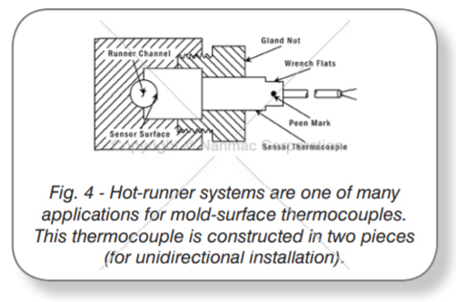
Since the sensing tip of surface thermocouples can be machined to match any surface contour, these thermocouples can even be installed in hot-runner systems. Figure 4 shows a typical installation. Either the surface or adiabatic-type probe can be used.
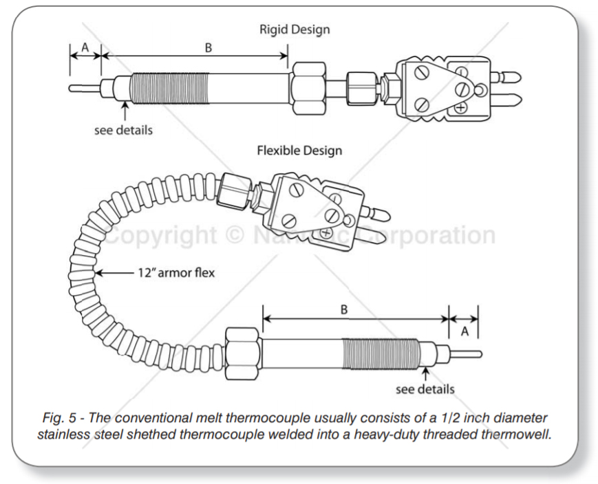
- Conventional Melt Thermocouples
The conventional thermocouple is used for measuring temperatures inside the extruder barrel or molding machine nozzle is shown in Fig. 5. It consists of a heavy-duty threaded thermowell (B) usually firmly welded or brazed into the thermowell with the desired protrusion (A). In instances when measurement of the inside surface temperature of the extruder wall is desired, the protrusion of the sheathed thermocouple (A) is simply reduced to zero, making the thermal junction flush with the surface. When the temperature of the flowing plastic is to be measured, the sheathed thermocouple is extended up to a maximum of 1 inch (if the throat diameter of the sheathed extruder permits it). In some instances, the tip of the threaded thermowell is modified so that a thick, long cylinder of ceramic of fluoropolymer insulator can be installed to surround and isolate the 1/8 inch diameter thermocouple. This thermal insulation is designed to reduce conduction errors, thereby improving the overall accuracy of the melt-temperature measurement.
There are two inherent limitations in the design of the conventional melt thermocouple, namely slow response time and conduction errors. The response time of the sheathed thermocouple is too slow to measure rapidly changing temperatures in cyclical applications such as injection molding. Since all of these thermocouples are installed perpendicular to the plane of heat flow, large conduction errors exist whenever there is a temperature gradient. The thermocouple senses a temperature that is very closely related to that of the large heat sink—the barrel wall—rather than the true melt temperature.
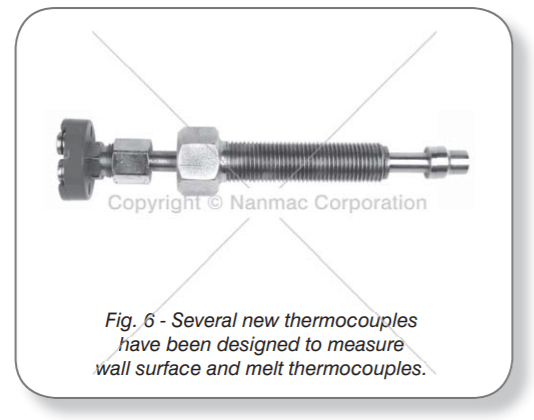
New melt thermocouple designs are several thermocouples, designed to measure the wall surface temperature and melt temperature are shown in Fig. 6. If the wall surface temperature is to be measured, the thermal junctions are the electrically grounded type, similar to the thermocouple described above for measuring part temperature. The tip of the sensor should protrude about 0.04 - 0.05 in. into the melt stream, because, in addition to boundary layer effects, in some instances the plastic flowing in the nozzle momentarily sticks to the inside surface, acting as an insulator. When this happens, the thermocouple does not sense the true melt temperature.
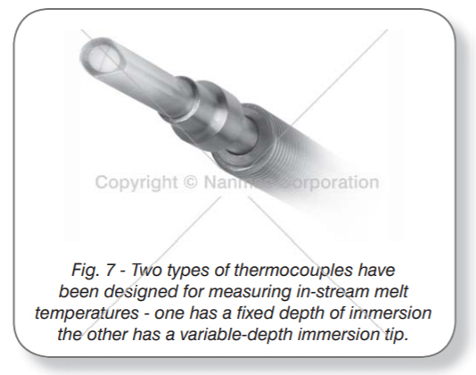
- in-stream
In-stream plastic temperature measurements are occasionally required to determine, among other things, the mixing characteristics of the melt, the efficiency of the screw, and the bell-shaped temperature profile across the melt stream. Fig. 7 shows a typical thermocouple design which has been successfully used to measure in-stream melt temperatures and temperature profiles across the flowing stream. All thermocouples for this application are of the adiabatic type. Since these sensors are subjected to very highly viscous materials (over 200,000 poise) at high pressures and temperatures, that portion of the thermocouple in the stream is teardrop-shaped to minimize the shear effects on the thermowell. The sensing tip is installed on the inclined plane of the tip for self-cleaning purposes. These thermocouples are unidirectional—the two-piece construction allows the units to be installed with the wedge facing upstream into the oncoming plastic. A peen mark is provided at the connector end for orientation purposes. There are two styles of immersion thermocouples. One version has a fixed depth of immersion; the other has a variable-depth immersion tip that can be adjusted in increments equal to a thread width when the extruder is stopped. Both styles have sufficient accuracy and sensitivity to measure the local temperature of the flowing plastic.
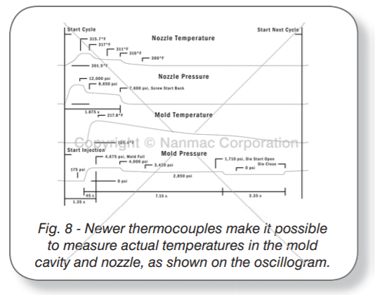
With more accurate, faster responding temperature sensors, such as those described above, it is now possible to measure actual temperatures in the mold cavity or extruder, rather than just the peak or average temperature. Fig. 8 is a reproduction of an actual test oscillogram showing both temperature and pressure vs. time data in both the nozzle and the injection mold cavity during a single injection cycle. Note the correlation between the response times and the important events occurring in a typical injection cycle. The temperatures were recorded using ribbon-type thermocouples similar to those shown in Fig. 6.
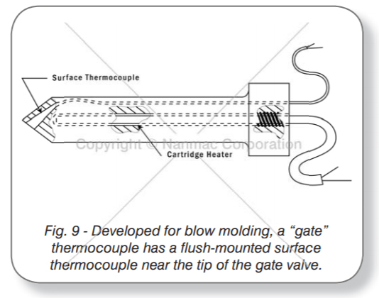
Occasionally, there is a requirement in blow molding to measure the surface temperature of the gate valve, in order to control its temperature more accurately. This can be accomplished by installing a surface thermocouple with a tapered thermowell into the gate valve. The thermocouple is press-fitted into a mating tapered hole in the gate, and any excess material that may be protruding is ground off. The completely installed unit has a flush-mounted surface thermocouple near the tip of the gate
This thermocouple may be used to monitor the temperature of the plastic and control the cartridge heater. The extension leads are brought out via a milled groove on the side of the gate. A typical installation is shown in Fig. 9.
There are two inherent limitations in the design of the conventional melt thermocouple, namely slow response time and conduction errors. The response time of the sheathed thermocouple is too slow to measure rapidly changing temperatures in cyclical applications such as injection molding. Since all of these thermocouples are installed perpendicular to the plane of heat flow, large conduction errors exist whenever there is a temperature gradient. The thermocouple senses a temperature that is very closely related to that of the large heat sink—the barrel wall—rather than the true melt temperature.
Dr. Ing. Helmut Gormar, et al, “Thermocouples with Increased Measuring Accuracy for Plastics Processing Machines,” Industrial and Production Engineering, Jan. 1980
© 2025 Nanmac Corporation
