


Contact Us
Temperature Transmitters
Wire Harnesses
Temperature Sensors
Fiber Optic Sensor Systems (Partner Company)
Thermocouple/Extension Wire
Temperature and Process Controllers
Specialty Metals


Whitepapers / Leading Cause of Errors in Temperature Measurement
All contact type of temperature sensors such as thermocouples, RTD's, thermistors, bi-metallic thermometers, etc. are subject to an error we call the “STEM EFFECT' (SE). When a probe is immersed into a gas or a liquid environment, a new thermal conductive path is created by the probe's stem. Thus, heat is conducted away from the sensing tip via the probe's stem to the outer atmosphere. This results in the sensing tip reading a temperature which is lower than the surrounding gas or liquid
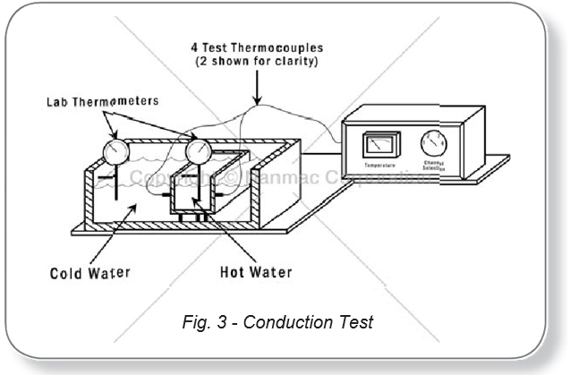
Several years ago, NANMAC conducted an experiment to determine the magnitude of the errors produced by the “Stem Effect.” The experiment consisted of a container of hot water surrounded by a reservoir of cold water. The hot water was kept hot by an immersion type heater and the cold water was kept cold by a simple circulating pump and cooling radiator. A gradient of about 80 degrees Fahrenheit was thus maintained over extended time periods.
The temperatures in the hot and cold reservoirs were continuously monitored by laboratory thermometers with an accuracy of + .5 degrees Fahrenheit. The carbon steel hot water tank had a dimension of 5” OD with a wall of 1/2” thickness.
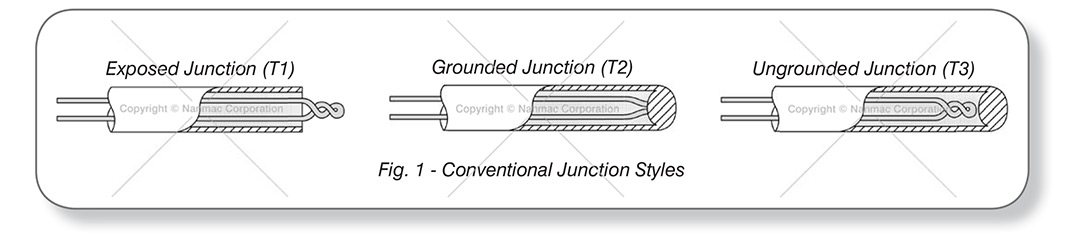
Four thermocouples, (Figs. 1 & 2) each with a different style of thermal junction,were installed in the wall of the hot water tank and aligned flush with the inner surface of the tank. All thermocouples were in direct contact with the hot water. All units had iron/constantan elements and the outputs were monitored by the same pyrometer through a thermocouple selector switch. In addition, all thermocouples were made from the same lot of wire and resistances were matched- Fig. 3 is a schematic of the test setup.
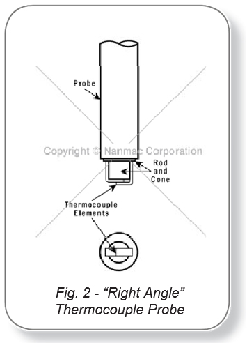
Thermocouples T-1, T-2 and T-3 are conventional type thermocouples, and T-4 is the “Right Angle” unit with ribbon elements. Table 1 shows the actual measurements made over a 16-hour period covering two consecutive days. The conventional style thermal junctions produced errors of from 10% to 66% in the observed temperature changes while the “Right Angle” thermocouple showed no measurable errors due to conduction.
The Patented “Right Angle” thermocouple features a thermal junction at right angles to the longitudinal axis of the probe. The thermal elements consist of ribbons electrically welded together at the sensing tip. These ribbon elements are brought out to the opposing sides of the probes along the interface of a rod and cone assembly made out of high temperature insulation. The ribbons in the vicinity of the thermal junction are parallel to the plane of heat flow. Thus both the thermal junction and the ribbons are heated simultaneously and conduction errors are minimized. The distance from the junction to the corners of the ribbon elements divided by the junction thickness produces a ratio of 20 to 1. This ratio is the reason why the ribbon thermocouples have an insignificant error caused by the “Stem Effect.” Ribbon elements also have response times in the low milliseconds to transients.
The junction formed for microsecond response time will typically need to be remade after each use. Keep in mind; the response time of any thermocouple is directly related to the size of the thermal junction. In order to provide a device that has microsecond response, the junction must be microscopic. This size of a junction will not last long under “clean” conditions. In other words, if the temperature to be measured is in a harsh environment, such as an interface temperature of two materials, of a “dirty” gas flow, the thermal junction will be made and renewed by the interface of blast. If the temperature is a “clean” temperature, then the junction may be swept away and require the aforementioned maintenance. This does not mean that it will not react to and measure, the temperature of interest, it may though require the maintenance described here after use. The device will continue to work after maintenance is performed until about 1/2 inch has been removed from the sensing tip. Hence the name “Eroding Junction Thermocouple.”
| Temperature Measurement (°F) | |||||||
| Reading No. | Cold Water | Hot Water | T | T1 | T | T3 | T4 |
| 1 | 104 | 174 | 70 | 169 | 154 | 127 | 175 |
| 2 | 104 | 174 | 70 | 166 | 157 | 127 | 175 |
| 3 | 104 | 175 | 71 | 167 | 151 | 127 | 175 |
| 4 | 104 | 175 | 71 | 167 | 151 | 124 | 175 |
| 5 | 102 | 174 | 71 | 167 | 151 | 125 | 174 |
| 6 | 102 | 175 | 73 | 167 | 152 | 126 | 175 |
| 7 | 102 | 175 | 73 | 167 | 151 | 125 | 175 |
| 8 | 90 | 175 | 85 | 167 | 150 | 120 | 175 |
| 9 | 93 | 185 | 92 | 178 | 157 | 127 | 185 |
| 10 | 102 | 190 | 88 | 182 | 165 | 135 | 191 |
| 11 | 102 | 190 | 88 | 180 | 163 | 133 | 190 |
| 12 | 100 | 188 | 88 | 180 | 160 | 130 | 188 |
| 13 | 102 | 189 | 87 | 180 | 160 | 130 | 189 |
| 14 | 103 | 189 | 86 | 180 | 160 | 132 | 188 |
| Average | 101.0 | 180.6 | 79.5 | 172.6 | 155.9 | 127.7 | 180.7 |
| Error (°F) | -8.0 | -24.7 | -52.9 | 0 | |||
| % Error | 10.1 | 31.1 | 66.5 | 0 | |||
© 2025 Nanmac Corporation
