


Contact Us
Temperature Transmitters
Wire Harnesses
Temperature Sensors
Fiber Optic Sensor Systems (Partner Company)
Thermocouple/Extension Wire
Temperature and Process Controllers
Specialty Metals


Whitepapers / Thermocouples in Furnaces & Ovens
The temperature on the inside of furnaces and ovens are commonly monitored and controlled by thermocouples inserted into the heated chamber. The one common feature of all furnaces is the fact that there are isotherms within the heated chamber. Isotherms are regions of equal temperatures. They are similar to the contour lines on a map illustrating areas of equal altitude. Isotherms are caused by gradients within the furnace created by uneven heating, inadequate circulation, uneven distribution of the work load within the furnace, etc. There are also isotherms within the wall of the furnace since the outside surface temperature of the wall is close to ambient temperature and the inside surface temperature of the wall may be 3,000 degrees Fahrenheit or more.
Thermocouples are installed in the furnace by machining an appropriate hole through the wall. The thermocouple now cuts across a myriad of isotherms and creates a conductive path for heat to flow from the hot area to the cool area. The thermocouple (since it measures its own temperature) is constantly being cooled by this conduction. The end result is the output of the thermocouple is always in equilibrium with the heat coming into the junction and the heat being carried away by conduction via the thermowell to the outer jacket of your furnace and the atmosphere. We call this error the “Stem Effect.” This error is influenced by the heat conduction in the wires, insulation and the sheath or thermowell of the thermocouple. It is virtually impossible to predict the magnitude of this error. Even if you could determine this error at a particular temperature, it would change as the temperature changes since the thermal conductivity of all materials varies with temperature.
In order to minimize the “Stem Effect” error one must install the thermocouple parallel to the plane of heat flow for a distance of at least 20 diameters of the probe. If you use an 1/8” OD probe, then 2-1/2” inches of the tip of this probe should be located parallel to the plane of heat flow.
Furnace Probes
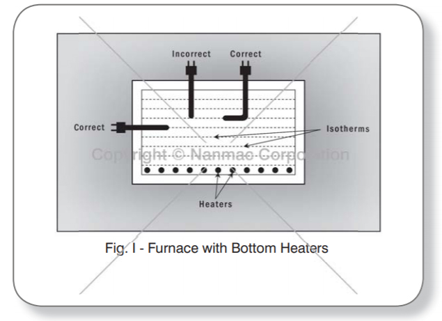
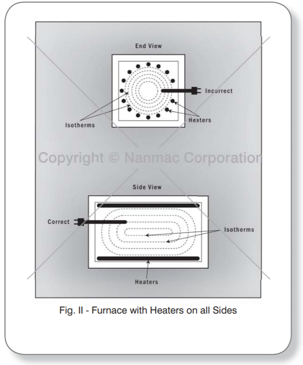
Fig. I is a schematic of a furnace with heating elements at the bottom. The isotherms are shown as dotted tines. Fig. 11 is a similar sketch showing the isotherms in a furnace with heaters on all sides. In both sketches the correct orientation of the temperature sensors has been illustrated. In all instances, the correct orientation requires that the thermocouple extend parallel to the isotherms for a length equal to 20 times the probe diameter. A 3/8” diameter thermocouple probe thus should be inserted for a length of 7-1/2” inches along the isotherm.
Accuracy of temperature measurements made within furnaces can be greatly improved if the temperature sensors are installed parallel to the isotherms for a distance equal to 20 times the diameter of the protection sheath. This will reduce the “Stem Effect” (error caused by conduction in the sheath, wires and insulation) to an insignificant amount.
The basic physical principles involved are as follows:
- Heat is always exchanged between two objects at different temperatures and it always flows from the hotter to the cooler object and...
- Heat cannot be exchanged between two objects at the same temperature. Our objective is to design and install a thermocouple into a furnace so that the thermocouple sensing tip is always in equilibrium with the temperature of interest and therefore accurate measurements are being made.
© 2025 Nanmac Corporation
